I managed to end up with an old vector network analyser, which I was fortunately able to fix. It is a Rohde & Schwarz ZVCE 20 kHz - 8 GHz, 2 port VNA. Below, I'll show you how it ended up basically being a bunch of dead tantalum capacitors that almost wrote off an entire instrument. What a shame that would've been!
First Impressions
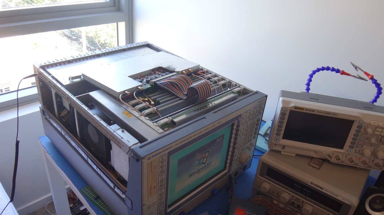
When I got the VNA in late 2017/early 2018, I was told that it hadn't been turned on for quite a while, and people were unsure of its state. I put it outdoors, turned it on, and smoke started billowing out the side. I turned it off straight away, and was pretty shocked. How on earth would I ever be able to fix this thing? I decided to open it up, and see if I could see the source of all this smoke.
Scorch Marks
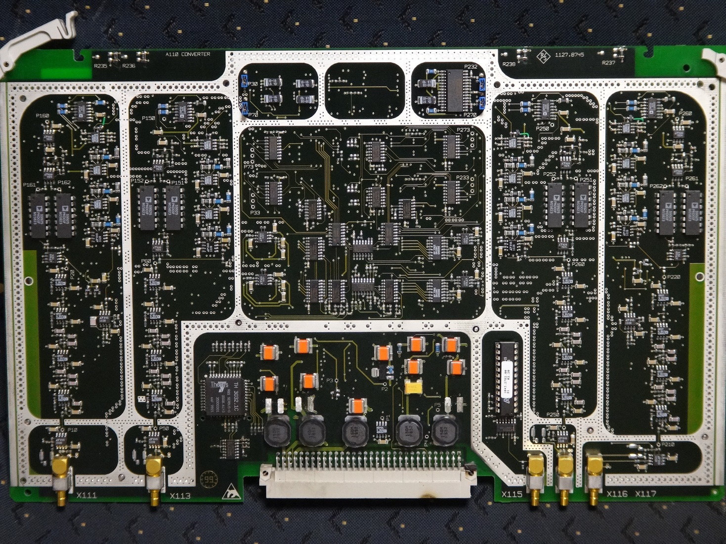
I pulled out cards one-by-one, until I saw something a little suspicious on a card that was labelled "Converter". Three capacitors had exploded, and left craters behind.
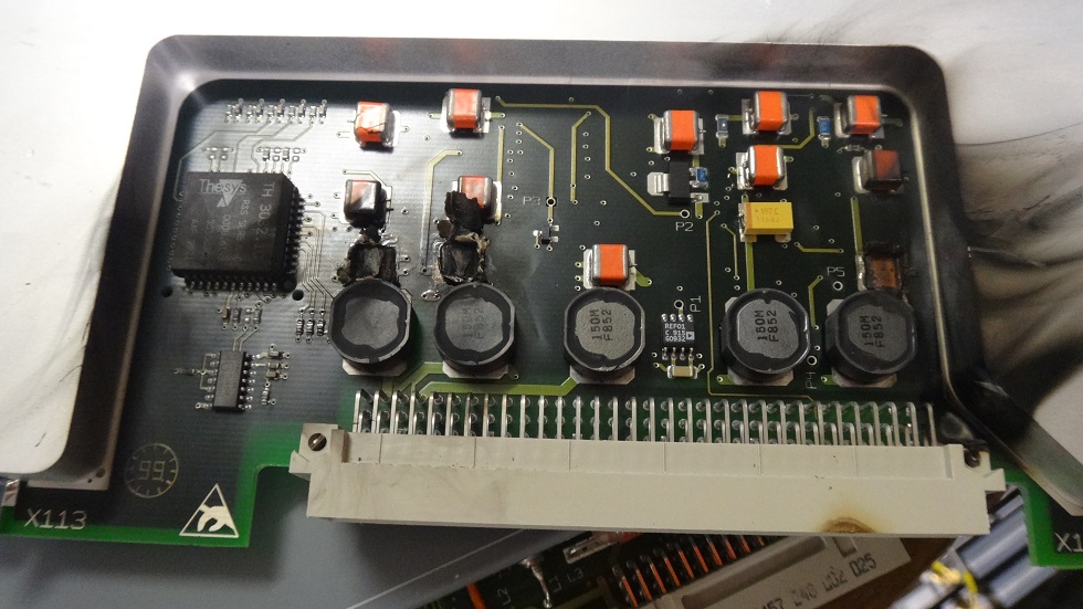
I cleaned up the capacitor remains and the surrounding gunk, and fortunately there was no damage to the PCB. I wouldn't have been able to fix that.
Turning it on, Round 2
After cleaning up the dead tantalums, I plugged the card back in, and no smoke came out this time. I guess that means I had made progress. It booted up with Windows NT, and the measurement software loaded up. I thought I had done it until an error popped up "ERROR: OVERLOAD ON PORT 1". Nothing was connected to either port 1 or 2, so I figured it must have been something internal.
I followed a few red herrings at this point, which I will quickly summarise, so that this doesn't drone on forever. I tried pulling apart RF cabling, and looking at various submodules on a spectrum analyser. I took shielding off other cards, but I couldn't find anything. I got a bit discouraged and the VNA was just a paperweight for several months.
Fixing it
One day, I had finished making an RF PCB with some distributed filters, and I wanted to test it, but with no VNA, that was difficult. I got permission to look at it on a VNA at my workplace, and suddenly, I could see exactly what my circuit was doing. The ability to test home RF PCBs gave me that final jolt of motivation to fix the VNA.
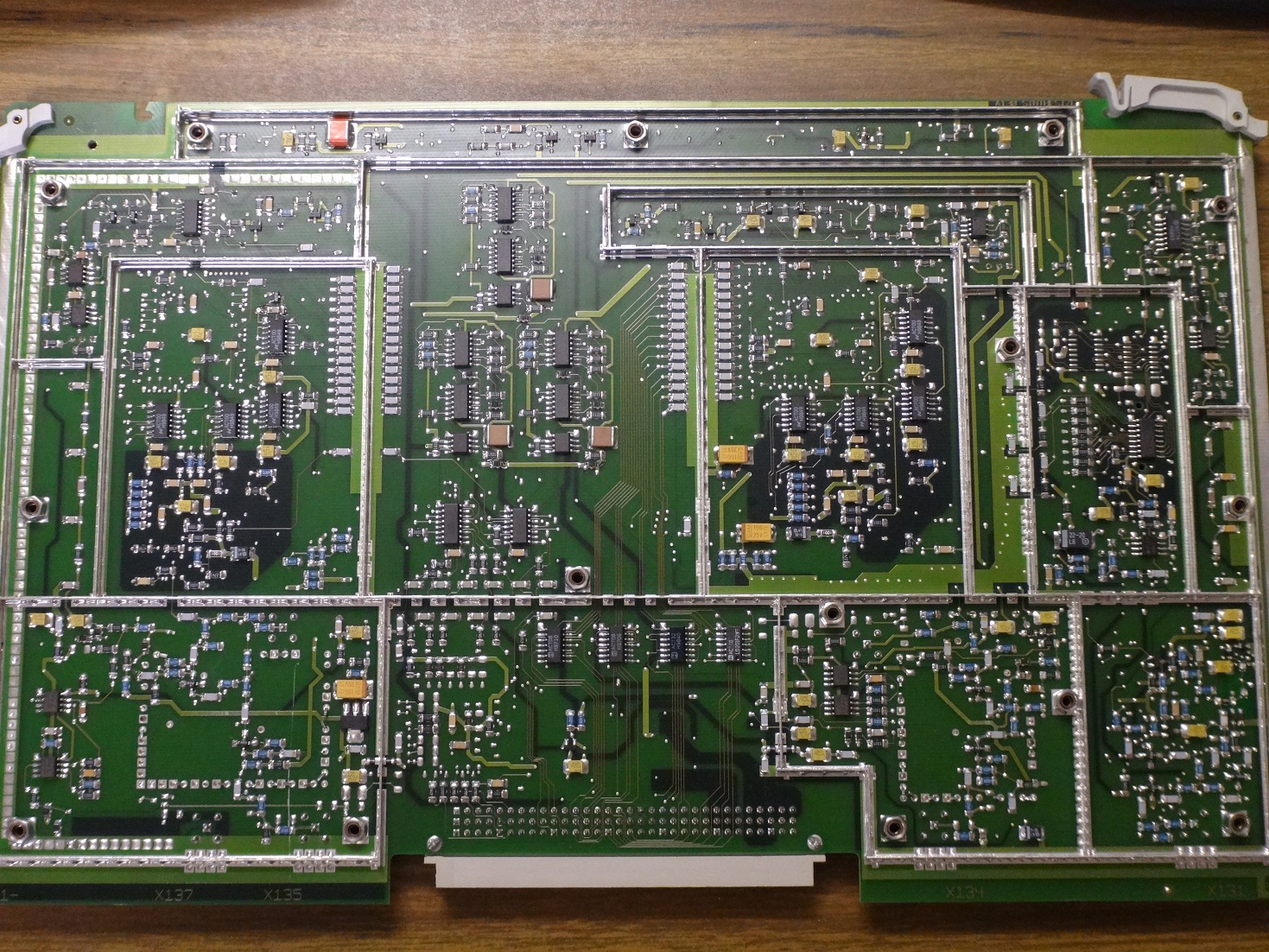
I went back to the obvious, the converter card. That was where the tantalum capacitors had blown up. Maybe an IC or something was dead on that board that was causing the overload error. The trouble was that I couldn't probe the card while it was in the VNA, so I bought SMB cables to jump out the RF connections, and breadboard jumper wires to break out the 96 pin DIN backplane connector.
There were op-amps, peak detectors, and an ADC. I probed what looked like 4 independent channels (one of which is totally disconnected in the VNA). One of them had voltage rails that made sense on all of the decoupling capacitors, and ICs, but the other 3 channels had nothing. I couldn't see anything obviously dead, so I kept probing, and looking through datasheets.
Eventually, my brother, who is also an electrical engineer, offerred me his thermal camera. I don't know if you've ever used one for debugging circuits, but they're amazing. I turned it on the board (unfortunately I didn't save screenshots, they were pretty cool), and the working channel was quite warm, and the other 3 were cool. There were some ICs in the centre of the board that seemed hot, so I tried to lift their legs, to see if the rest of the board would work, but nothing quite happened.
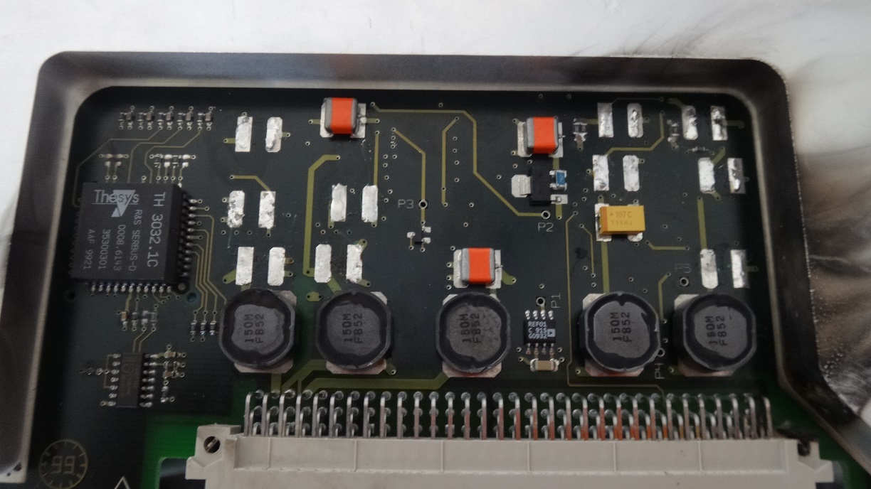
Then, I finally returned to the obvious place: the tantalum capacitors. I probed a bunch of them, and there was no voltage across some of them, which seemed odd. I turned off the VNA, and found that a number of them had failed, and turned into resistors of 10 ohms or less. One by one, I pulled out the capacitors, turned on the VNA, and more voltage rails came back to life. As of today, the board is 8 capacitors lighter. I haven't yet replaced them, as I don't want the cards to fail all over again. It looks like they were 100uF or so, and they can be bought online. The capacitors appear to have had a rating of 25V, but some rails were a touch over 14V, which may not have been enough derating for long term operation.
I have decided not to replace the capacitors for now, as they only seem to be doing some filtering and decoupling at the input of the converter card. I'm not doing very precise measurements, so I wanted to see if I could survive. Currently, with my homemade cal kit, it seems to match modern, in-service, VNAs quite well, so I'm happy.
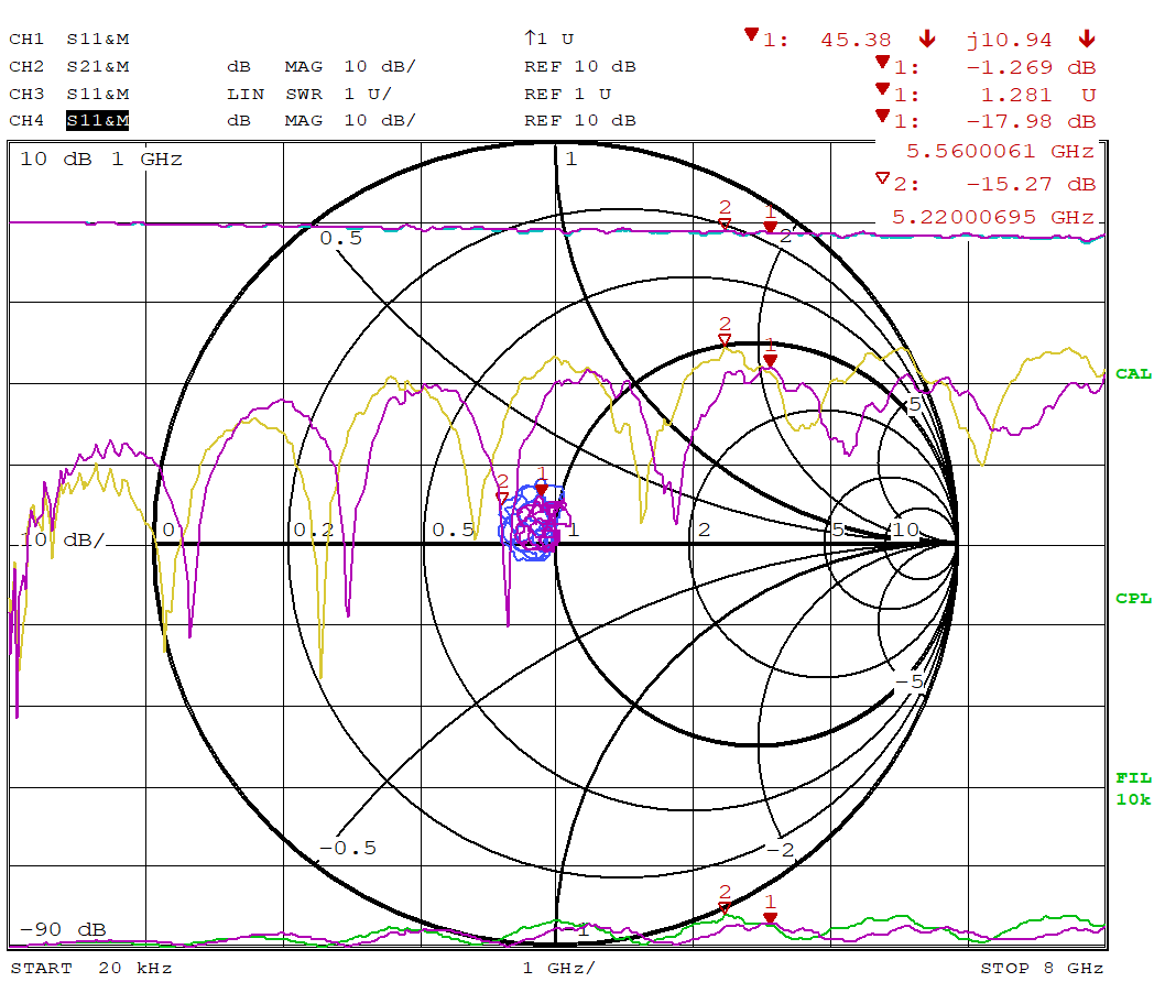
Here's an overly convoluted measurement I made when it was all working. Out of interest, the pink traces show the performance of a through line after I trimmed connector pins. The other coloured traces show slightly worse return loss, which is before the pins were trimmed.
Once I finally got on task, it was done in one weekend. Sometimes all you need is that last push!
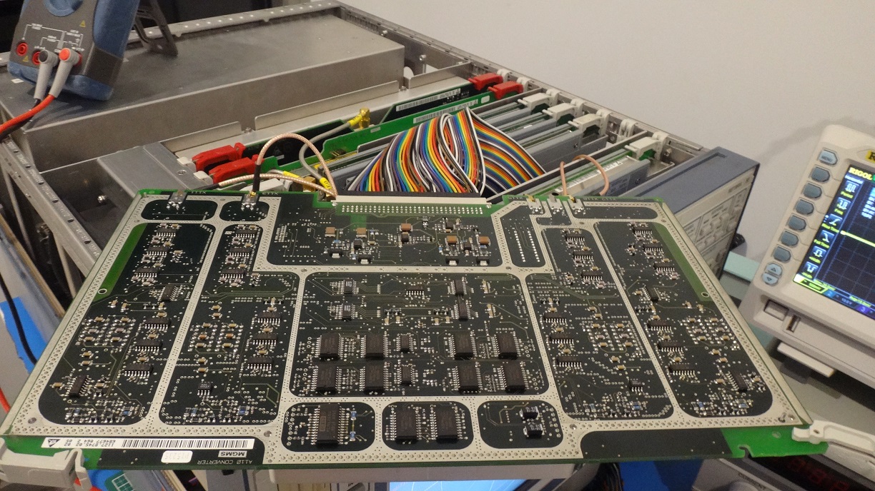
Bonus Photos
The converter card being debugged
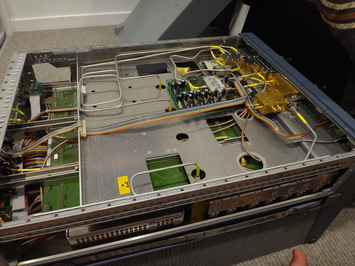
The synthesiser card top side opened up
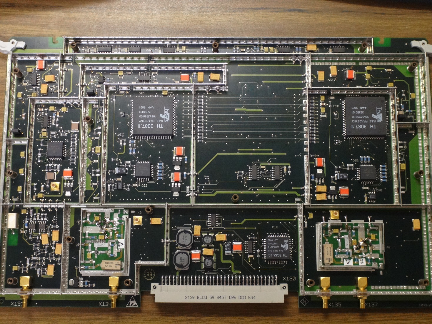
The synthesiser card bottom side opened up